
I knew from the start that we would have to ultimately build five different versions of our machine; a proof of concept game, a prototype game, a production whitewood game, engineering sample games (10 units), and the finally the production games (20 units planned). Seasoned manufacturers do not generally build a proof of concept game, but since we had zero experience building any amusement device we felt it would be necessary.
Still, there was the issue of just where to start this daunting process. Due to a general lack of direction we settled on 3D printing. Many of the old parts in this machine would have to be 3D printed because of the low production volume planned. It was up to Alex to draw and 3D print the first few pieces; the pieces that made up the lift mechanism. We settled on this mechanism because it seemed easy enough to remove from the game.
Turns out that this seemingly harmless mechanism was a bit more stubborn than we anticipated. One week of trial and error (and waiting for the damn 3D printer to s-l-o-w-l-y print the parts) resulted in a few prototype parts that we were happy with. All the parts of the mechanism had to be redesigned and reinforced so they would have the strength of the original (pot metal?) parts. It was a good feeling to put the new parts in the old machine and watch them successfully lift the small ceramic balls up to the playfield. Little did we know at the time that we would be designing and tweaking 3D printed parts non-stop for months to come. Without a 3D printer a small project like this would have been impossible.

Encouraged by the small successes of our 3D printing attempts, we then set our sites on drawing the playfield in SolidWorks. This job would fall to Alex. The original Contact Master had a somewhat complex layering of what is really four playfields, not the traditional singular playfield of modern pinball machines. There is the *paperclip* (the playfield that makes up the border and shooter lane), the top playfield (the actual playing surface of the game), the reset playfield (when moved it allows the balls on the top playfield to drop through the holes), and the bottom playfield (how the balls return to the front of the game and rejoin the queue for the lifter mechanism). This playfield also houses the contact switch and solenoid assemblies. In Contact Master, three of these four playfields interact independently from each other making its operation somewhat unreliable. We made the decision to have all four of these playfields interlock together in what came to be known as the playfield sandwich.

The only playfield of the four that was of any immediate concern was the top playfield. We would need this playfield in order to build our first proof of concept cabinet. Paul from VirtuaPin Cabinets CNC routed this playfield and Jose began the task of building a very crude cabinet around it. Once we had these two basic elements in place and were happy with壯陽藥
them as a rough working model, Jose then built the lower playfield. This gave us a very basic building block to start working on the mechanical assemblies.


There is only one switch in Contact Master and we remained true to this in ScoreGasm Master. However, the switch design and how they are wired to the power supply turned out to be very different from each other. One of our goals from the beginning of this project was to use actual pinball parts when possible, Contact Master used virtually no parts that made the move to the pinball machines that would came after it. The switch assembly in Contact Master was both overly and poorly engineered. It involved a teeter totter type of mechanism that was wired using bolts to pass the electric power from under the lower playfield to the top side of said playfield. It was rickety to say the least. We decided to use a slightly modified 5647-12693-19 switch coupled with a 3D printed trough to more eloquently achieve the goal. This switch has a very low amperage rating however, so we had to add a relay circuit as this switch was to be charged with the task of firing the 2 solenoids in the game. The solenoid assemblies were also redesigned to use modern pinball parts.


ScoreGasm Master also requires a shooter mechanism, a reset mechanism, a lift mechanism, and a tilt mechanism. In Contact Master the shooter mechanism uses a very thin shooter rod and a pot metal shooter housing. the reset mechanism is coin operated, the reset mechanism is made of pot metal, and the tilt mechanism is a very unique part imbedded in the top playfield that is visible from the player’s perspective. Keeping with the idea of using pinball parts whenever possible, we redesigned the shooter mechanism to use a modern shooter rod and beehive housing. We redesigned the reset mechanism to be non-coin operated and also use a modern rod and beehive housing set up. The lift mechanism was redesigned from the ground up to accommodate 3D printed plastics. The tilt mechanism we left alone. We redesigned it for 3D printing, but left the style and placement exactly the same. All four of these mechanisms were installed in our proof of concept cabinet and tweaked until operational.


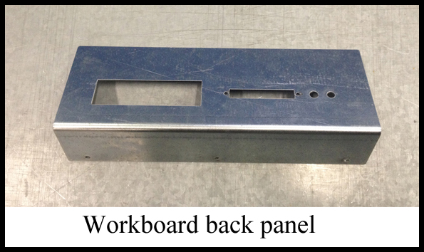
Although 3D printers are pretty much magic, we still ran into quite a few parts that would have to be fabricated from metal; the shooter, lift, and reset mechanism mounting brackets, the playfield reset bracket, the tilt mechanism reset bracket, the tilt mechanism finish panel, the speaker housing finish panel, the workboard back panel, and the leg mounting protective brackets. Dino came through with the prototyping and manufacturing of these parts in a very short amount of time.
It was at this point that I realized the project was far too big for me to manage, so Andrew stepped up and took on the role of production manager. This turned out to be a good move to keep the project moving ahead and on schedule.
To bring ScoreGasm into the 21st century we decided to add a sound track and call outs. Scott and Andrew began researching and testing different power supplies, wav trigger boards, amplifiers and power modules at about the same time we started working on the playfields. Both were working somewhat independently of each other and we feared this would lead to needless work duplication so we scheduled our first SGM team meeting on Dec. 5th, 2014. By the time this meeting rolled around Scott had some basic music tracks and call outs programmed on a wav. trigger board and had them hooked up to a amplifier and speaker on a workboard. Andrew had made a workboard as well and had wired our cabinet so that it was very roughly playable. Together they had completed our proof of concept machine. While this was a big victory, it was only the beginning of the journey and we all knew it.


